Table of Contents
3-Channel Ideal Diode Board w/Priority
Welcome to the technical documentation for the 3-Channel Ideal Diode Module. This page provides a bit more in depth information about the product than fits in the product page.
What makes this board special?
All the ideal diode modules we've found on the market do NOT have the ability to turn off. Many of the ideal diode controllers themselves cannot be disabled, and even when they can be, the MOSFET's body diode is still conducting and powering the downstream device(s). If you want one of the other modules you can find elsewhere to turn completely off, you need to wire a switch upstream of the module. If you wired a switch downstream, the ideal diode module would still consume power from your battery!
So to implement a true shutdown, you'd then need one switch, relay, or “MOSFET switch module” per input (in order to keep all the inputs isolated). A DPST relay could help you connect two inputs, but then you still need a way to trigger the relay from either of the inputs without guarantee of which input is present at any time.
Finally, if you want to have any sort of “Priority” logic, where a designated input (from an AC wall adapter, say) would always take precedence over a battery, even if the battery voltage is higher and would otherwise power the downstream device, you'd need some extra circuitry to make that happen.
By the time you're looking at implementing all the above, across three channels, those modules don't seem so cheap anymore.
Internal at BrownieBoards, we needed a solution that checked all the boxes above: One switch for 3x inputs. Zero power consumption unless enabled. Priority input overrides battery input(s). So we made this product.
One switch completely disables all three inputs, without compromising isolation, bringing board power draw down to the equivalent rate of battery self-discharge. Nothing is actually powered on the board when the switch is “Off” - the only current is reverse leakage current through a diode, nominally in the nano-amp range.
And then for good measure, we made the “priority shutdown” feature configurable via jumper. Just because we'll always need a certain behavior in our circuit, doesn't mean you will!
Overview
We needed an ideal diode circuit, which would prioritize a specific input over the others, while allowing hot-swappable batteries on the “backup” inputs. With those requirements in mind, we came up with this board! The 3-Channel Ideal Diode Module is designed to manage power from multiple sources, such as batteries and an AC power adapter, while ensuring seamless switching and prioritization. By integrating ideal diode controllers with P-channel MOSFETs, this module minimizes power loss and enables highly efficient operation.
Key Features
- Input prioritization for seamless switching between power sources.
- Three independent channels with low forward voltage drop (about 14mOhm resistance in-to-out).
- Reverse polarity protection on all inputs. (assumes isolated supplies, see below)
- Configurable input behavior: Normal Priority, All-Channel with Priority shutdown, and All-Channel with global shutdown.
- Microcontroller integration for voltage monitoring and shutdown control.
- Ultra-low current draw (<5 µA) when disabled.
- Multiple input connection options: 2.54mm Dupont headers, 5mm terminal blocks, PCB-mount XT60 connectors, or direct 12AWG wire connection.
- Optional heatsink installation to increase safe current rating from 15A/channel to 20A/channel.
- Made with high-quality, name brand components. Diodes Incorporated MOSFETs, YAGEO resistors.
How It Works
Ideal Diode Functionality
An ideal diode replicates the unidirectional current flow of a traditional diode but with significantly lower forward voltage drop. This is achieved using MOSFETs controlled by specialized circuitry, which ensures high efficiency and reduced heat dissipation.
Input Prioritization
The module allows a lower-voltage source (e.g., 12V power brick) to take priority over higher-voltage backup inputs (e.g., 3S or 4S batteries). If the priority input is removed, the backup inputs automatically take over, ensuring uninterrupted power delivery to the output rail.
Monitoring & Control:
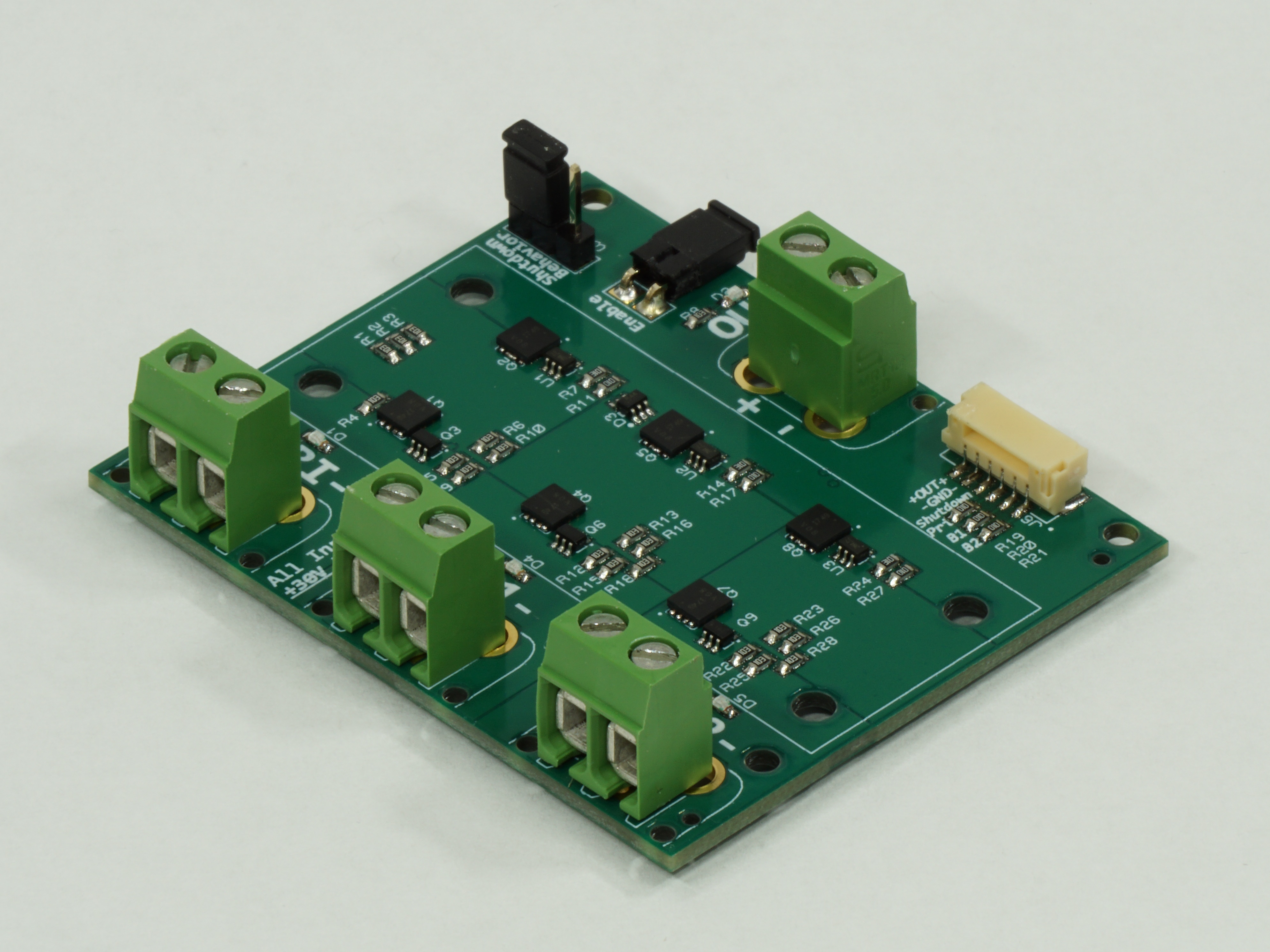
Board Enable and Priority Shutdown Behavior
 Enable Jumper: Disconnects all inputs when open, reducing current draw to <5 µA.
These pins are floating contact - don't connect a microcontroller to the “Enable” pin and expect you can set a “HIGH” or “LOW” value to disable! Any current through the enable pin will result in the board turning on. If you must use this feature with a microcontroller, you must use a relay or similar with this connection.
Input Shutdown Behavior Select jumper settings to configure how the backup inputs behave:
- Normal Priority Operation: (jumper across pins 1&2)
- Backup inputs are disabled when the Priority input is present.
- Shutdown affects only the Priority input.
- All-Channel Operation (Priority Shutdown Only): (jumper removed)
- Backup inputs are active even if Priority Input is present
- Shutdown affects only the Priority input.
- All-Channel Operation (All Inputs Shutdown): (jumper across pins 2&3)
- Backup inputs are active even if Priority Input is present
- Shutdown affects all inputs, de-energizing the output rail.
These settings are also printed on the back of the module, so you don't have to worry about forgetting how to configure it!
Microcontroller Integration Connector

A 6-pin JST-GH connector provides an easy way to integrate with a microcontroller. Feel free to leave this disconnected if unused.
The pinout follows:
- Output Rail
- Ground
- Shutdown (Logic-level control, >2V to activate)
- “Priority” Voltage Monitor (protected by 100KΩ resistor)
- “Backup 1” Voltage Monitor (protected by 100KΩ resistor)
- “Backup 2” Voltage Monitor (protected by 100KΩ resistor)
Shutdown Control
The “Shutdown” pin provides fine control over input behavior: A logic-level High (>2V) will shut down the channels as configured by the “Backup Input Behavior”.
Shutdown Power - The board will still present an approx. 5kΩ load on inputs when channels are shut down.
Input Status LEDs
Each input channel has an LED indicating input voltage presence and input enabled status.
If the input is either disconnected from power, the board is disabled, or the specific input is shutdown (either via microcontroller or priority selection), the status LED will not illuminate.
Technical Specifications
Electrical Characteristics
- Input Voltage Range: 5V to +30V.
- Forward Voltage Drop: 200-300mV at max current. See Table 1.
- Maximum Continuous Current per Channel: 15A (20A with optional heatsink).
- Reverse Polarity Protection: Yes, on all input channels - see note below.
- Off-State Current Draw: <5 µA.

Table 1: Temp and V drop at various Current Draw
Reverse voltage protection will vary depending on any voltage present at the Output, with a maximum reverse rating of -30V. For example, if one input is providing +12V to the Output (or there’s a 12V battery attached to the Output connector), the minimum reverse voltage protection rating will be reduced to -18V, due to the Positive + Negative voltage adding up to the rated 30V differential limit.
Reverse polarity protection is only effective for power sources (like batteries) that do not share a common ground. This module has a shared ground plane across all input and output connectors, so if you connect a power brick “+” to an input “-” and you have another power brick connected correctly, you'll have connected one power brick's “+” straight to the others' “-”.
Physical Characteristics
- Dimensions: 50 mm x 60 mm.
- Optional Heatsink: Standard 1/8th brick DC-DC converter heatsink, increasing current rating to 20A/channel. High-Quality Aluminum Heatsink manufactured by Wakefield-Vette
- Mounting Holes: see image below for hole plot

Input Connection Options
- 2.54mm Dupont Headers: Rated for 3A.
- 5mm Terminal Blocks: Rated for 16A; supports 12-30 AWG wire.
- PCB-Mount XT60 Connectors: Rated for 30A (max 60A).
- Direct 12AWG Wire: Supported via the largest holes on the footprint.
Applications
- Redundant Power Systems: Maintain uptime by seamlessly switching between primary and backup supplies.
- Battery Management: Prevent reverse current during charging or parallel configurations.
- Solar-Powered Systems: Prioritize solar over battery input for efficiency.
- Portable Electronics: Minimize power loss for extended battery life.
Questions?
For further details or inquiries, contact us at brownieboards @ steven-brown.net